Depth well matching during data preparation
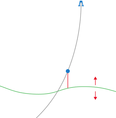
Horizons are moved vertically during well matching. click to enlarge
In the data preparation stage of the modeling process, when your data is still relatively raw, you can use the Depth Well Matching tool in the prepare > Post-Processing Tools strip to shift surfaces so that they match with the interpreted markers or point set(s). 'Surfaces' in this context refers to the 2D grid or tri-mesh representations of the event that you want to well match. The following event types can be well matched: horizons, faults, unconformities, intrusions, fluid contacts, fractures and maps.
When the TVD difference between the surface and the markers/point set (called 'residual') is very large, there might be an issue with the input data which should not be resolved through well matching. The tool allows you to QC the residuals in a dedicated view before the actual well matching is carried out. It is recommended to always review these residual values first, to see whether they reveal (lateral) trends, whether a bulk-shift of the surface(s) needs to be considered, or whether well marker interpretations need to be reassessed before proceeding with the well matching.
You can integrate well matching in workflow automation. In this case it's advisable that the selected target folder (where the well matched output surface will be saved) is a Surface Set or a Seismic Interpretation so that each time the well matching is repeated, the well matched (output) surface is overwritten and ready to be used in subsequent workflow automation steps (e.g. structural model building). Also, when a new well or well marker is introduced at a later stage and added to your input group of wells, it is automatically included in the well matching.
- You can well match surfaces of the following types of events: horizons, faults, unconformities, intrusions, fluid contacts, fractures and maps.
- All these events can be matched to markers as well as to point sets, except faults, which can only be matched to markers.
- To match an event with a marker or point set, it has to have a 2D grid and/or tri-mesh representation; the matched output surface will have the same representation as the input surface.
-
An event is only selectable on the form when the 2D grid or tri-mesh representation and marker (or point set) that you want to match to, belong to the same event. i.e. they carry the same name in the JewelExplorer. Matching to a point set also requires that the point set is stored in the same Input folder, next to the surface representation, see image below.
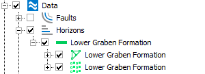
Matching to a point set requires that the point set is part of the same event in the same folder (in this example in the Data folder). click to enlarge
Guidelines on Source and Target folder selection
-
When the Target folder is set to 'Data', the well matched surface will receive a suffix (-WM) behind its name. When the Target folder is 'Seismic Interpretation' or 'Surface Set', the well matched surface will either be newly generated, or overwritten.
Suffix versus overwrite has a major impact on the auditability and repeatability of well matching:
- Preferred scenario The Source and Target folders are different and the Target folder is a Surface Set or Seismic Interpretation. This is the preferred scenario because the input surface will not be overwritten with the well matched surface. Because the well matched surface is written to a Surface Set or Seismic Interpretation, it can immediately be used in consecutive modeling steps. This makes this scenario applicable to Workflow Automation.
- Less recommended scenario The Target folder is the Data folder. When the Target folder is the Data folder, the well matched surface is created in a new event with a suffix (- WM) behind the name. Each time the well matching is repeated (e.g. with updated settings) a new event and surface are generated with a consecutive suffix. Auditability, QC and repeatability of this scenario is more limited than scenario 1 and therefore less suited for Workflow Automation. Also no Post Residuals property is generated when the target folder is the Data folder.
- Not recommended scenario The Source and Target folder are the same and either a Surface Set or Seismic Interpretation. In this scenario the input surface will be overwritten with the well matched (output) surface and therefore be lost.
For fluid contacts, fractures and maps this scenario is the only viable one as these types of events can only exist in the Data folder. - When you want to well match a fluid contact, fracture or map, the Target folder must be set to 'Data', as the Data folder is the only folder that can store these types of events.
Source Select the folder that contains the surface(s) that you want to depth well match.
Target Select the folder where you want to store the well matched (output) surface. See section 'Source and Target folder selection' under Before you start - guidelines.
Match to
- Marker Set Select this option if you want to match surface representations (2D grid or tri-mesh) only to markers.
- Point Set Select this option if you want to match surface representations (2D grid or tri-mesh) only to point sets.
- Both Select this option if you want to match surface representations (2D grid or tri-mesh) to point sets and to markers. Be aware that you cannot individually select to match Event A to a point set and Event B to a marker set; the well matching will always match to both representations if both are available.
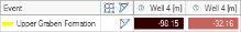
Marker set (Not applicable when matching to a point set) Select the marker set that contains the markers to which you want to well match. You can in/exclude markers for well matching via the 'Use for modeling' column in the Marker Table; if the 'Use for modeling' checkbox is unchecked the marker is excluded from well matching. As soon as one or more markers of your selected marker set are excluded (irrespective of the events in the selected Source), a warning icon appears behind the selection drop-down, see image below. You can ignore the warning if you are deliberately excluding markers.
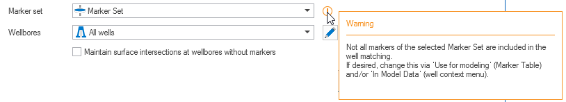
When not all markers in the selected marker set are included in modeling, you are warned via an info icon on the form. You can ignore the warning in case you are deliberately excluding one or more markers from your selected marker set. In/excluding markers is done via the 'Use for modeling' column in the Marker Table. click to enlarge
Wellbore(s) (Not applicable when matching to a point set) Select the well group that contains the wells with markers to which you want to match surfaces. The 'Well Data' item in the JewelExplorer is automatically set to 'All wells' (default well group containing all wells). If you do not want to match to all wells in the selected well group, click the pencil behind the drop-down and make a sub-selection of wells in the 'Wellbore selection' dialog that opens.
Maintain surface intersection at wellbore without markers (Not applicable when matching to a point set) With this option the depth of the surfaces at wells with no marker will be retained. If this option is unchecked, the residual interpolation can potentially affect the surface depth at wells with no markers.
On the Input tab, the input table shows the events (and corresponding representations) that are present in the selected Source. The 'Match to' column shows whether a marker or point set is available to match to by displaying the respective icons.
Event to Match This column lists all events with a 2D grid and/or tri-mesh representation in the selected Source, and the available representation. Select the event(s) that you want to depth well match and the representation (2D grid or tri-mesh) that you want to use as input. When the checkbox is grayed out, this is probably due to one of the following reasons (see also Before you start - guidelines above):
- You selected a radio-button under 'Match to' at the top of the form that does not correspond to the representation(s) you want to match to (marker set or point set).
- You forgot to select a marker set under 'Marker set' at the top of the form.
- The markers that you want to match to, do not carry the same name as the surface representation, hence they do not represent the same event.
- The point set that you want to match to, is not stored next to the surface representation in the same folder.
Per selected event, select the surface representation you want to use for the well matching (i.e. the 2D grid, the tri-mesh, or both). If you select both representations, the well matching will be carried out individually for each of the two representations.
Match to This column responds to the selection under 'Match to' at the top of the form and shows whether the event has markers in the selected marker set and/or whether a 'valid' point set is detected (i.e. a point set is 'valid' when it is stored next to the surface representation).
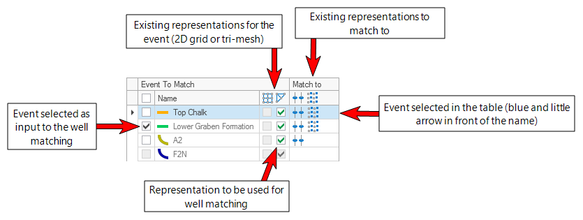
Explanation of the Input table. The events listed in the table are the events present in the selected Source; all four events have a tri-mesh representation (no 2D grid representation); Lower Graben Formation is selected as input to the well matching; events Top Chalk and Lower Graben Formation have a marker and a point set to which the surface can be matched, event A2 has a point set to which the surface can be matched, event F2N has neither a marker nor a point set to which the surface can be matched; Top Chalk is selected in the table (it is blue and has a little arrow in front of the row) which means it is eligible for the Residual Interpolation settings at the right side of the form. click to enlarge
Residual Interpolation
With the settings under 'Residual Interpolation' at the right side of the Input tab you specify, per event, how the residuals (once they are calculated) should be interpolated over the modeling area. The residual properties 'WM Residuals Pre' and 'WM Residuals Post', which will be created after 'Calculate' and 'Apply' respectively, are created based on these settings.
Event Select the event of interest in the Input table by clicking on it (it turns blue and a little arrow appears in front of the row). The name of the selected event will be displayed in light gray.
Method Select an interpolation method to construct the surfaces.
Inverse Distance Weighting This method uses the distance-weighted algorithm to interpolate the surface using the input locations as constraining input.
Ordinary Kriging (Legacy) This selection applies the geostatistical Kriging method to interpolate the property across the area. This type of Ordinary Kriging does not make use of the industry standard Kriging library and is performance optimized.
Power This option is only enabled when method Inverse Distance Weighted is selected. The Power is the exponent used for the weighting of the distances. Choose a value between 0.5 and 7.
Function This option is only enabled when Ordinary Kriging is selected. Specify the type of kriging: Exponential, Exponential power, Spherical, or Gaussian.
Major range This option is only enabled when Ordinary Kriging is selected. Specify the major range of influence of the input locations.
Minor range This option is only enabled when Ordinary Kriging is selected. Specify the minor range of influence of the input locations.
Azimuth(GN) This option is only enabled when Ordinary Kriging is selected. Specify the azimuth (to Grid North) of the axis corresponding with the major range.
Power (Ordinary Kriging) This option is only editable when the method is 'Ordinary Kriging' and the function is set to 'Exponential Power'. You can adjust the lateral extent of the kriging. Enter a value between 0 and 2.
Radius of influence Check the box to use a radius of influence and enter a value in the entry field. The radius of influence determines the distance over which you allow the interpolation of the residuals (and ultimately the well matching) to take effect. When matching to markers, the marker is the midpoint of the radius of influence; when matching to point sets (not enabled for well matching faults and 3D mesh structural models), each node of the point set is a midpoint of the radius of influence. When you leave the box unchecked, the interpolation takes effect over the entire modeling area (no limit).
Repeat the above steps for all the events that you selected as input to the well matching. You can right-mouse click on an event and copy-paste the settings to other events.
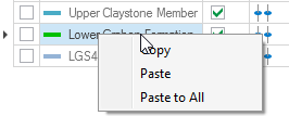
You can copy-paste the residual interpolation settings from one event to the other. click to enlarge
When you have finished the interpolation settings for each of the selected events, click Calculate at the base of the form and continue reading under Step 3 - QC the residuals.
After clicking 'Calculate' at the base of the form:
- The Residuals tab opens with the calculated residuals displayed in the table. A residual is the TVD difference between the input surface representation and the marker (or point set). In some cases an info-box may appear in the table cell, or a table cell remains empty. See Info-box and other scenarios in the residual table below for explanations of the info-box messages and other special scenarios.
- Per event, a residual property WM Residual Pre is added to the surface representation and to the marker (and if a point set was used, to the point set). The property contains the interpolation of the residual values, based on the settings as specified under Residual Interpolation on the Input tab (Step 2). The name of the property reflects how it was generated: it contains the source folder, target folder and representations used.
- In the Color Settings section on the form, the color scale is automatically scaled to the maximum absolute residual value and the colorset 'S_RedWhiteBlue' is auto-selected. You can change the color set and/or scale at any stage during QC by selecting/typing in the corresponding entry fields and clicking Update Colors.
Info-box and other scenarios in residual table
In some cases, no residual could be calculated, or a residual was calculated under special circumstances. In these cases an info-box with a short description of the issue is shown in the respective table cell. A cell can also remain completely empty, or an event can have multiple residuals in the same well. See below for an overview of all special scenarios that can occur in a table cell.
1) ![]() The cell shows an info-box but does not contain a residual value. The info-box can contain the following messages (note that these messages may occur simultaneously):
The cell shows an info-box but does not contain a residual value. The info-box can contain the following messages (note that these messages may occur simultaneously):
- No marker The wellbore does not have a marker for the respective event. This can also happen when the wellbore intersects the surface multiple times but not each intersection has a corresponding marker (see image A below).
- No intersection The wellbore does not intersect the surface of the respective event. Most probably the wellbore is located outside of the outer edge of the surface.
- Marker excluded via 'Use for modeling' The marker is not included in well matching as the 'Use for modeling' checkbox in the Marker Table is not checked.
- Wellbore excluded via 'In model data' The marker is not included in well matching as the 'In model data' option on the well's context menu is switched off. When 'In model data' is switched off, all markers of that wellbore are automatically excluded (grayed-out) in the 'Use for modeling' column of the Marker Table.
- Marker depth not defined The marker exists in the Marker Table but its MD depth is not defined.
- Cause unknown Another cause than the ones mentioned above has prevented the application from calculating a residual.
2)  The cell shows an info-box and contains a residual value. This means the residual was calculated under a special circumstance. The following message may occur:
- No intersection A marker is present for the wellbore but the wellbore does not intersect the corresponding surface due to the fact that the TD (total depth) of the wellbore is shallower than the surface. The residual is calculated via projection of marker on the surface (see image B below).
Special scenarios with no info-box in the cell
The following special scenarios can occur while no info-box is shown in the cell.
3)  The cell is empty (no value and no info-box). This is not related to any modeling issue but due to the arrangement of residual data in table format. More specifically, a cell may remain empty when:
- Another event has multiple markers.
- One event has only point set data, while another event has only marker data.
4)  There are multiple markers for one surface intersection. The application calculates the residuals for all these markers. In case you would proceed with the well matching, the application uses the marker closest to the surface (the other markers are ignored). The post residual property will show zero-residual for the used (closest) marker while the other markers keep a residual. Note that a horizontal well with multiple markers (one marker at each surface intersection) is a valid scenario. It is therefore recommended to always check the wellbore and markers when multiple residuals for one event exist.
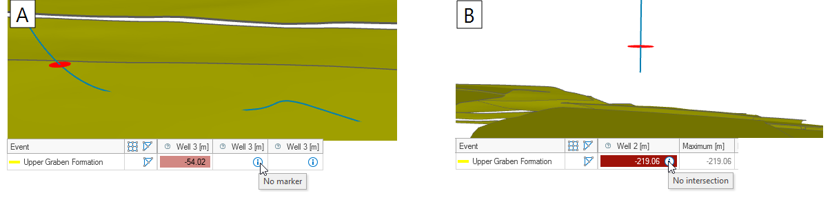
Image A: The wellbore intersects the surface three times but only one corresponding marker is detected. The other two intersections receive a 'No marker' message in the residual table. Image B: A corresponding surface and marker are detected, however, the wellbore does not intersect the surface. The marker is projected onto the surface and the residual is calculated anyhow (with an info-box warning displayed next to the residual in the table). click to enlarge
Before you perform the well matching it is important to review the residuals. They might reveal (lateral) trends, whether a bulk-shift of the surface(s) needs to be considered, or whether well marker interpretations need to be reassessed. There are two ways to QC the residuals: via the table on the form and by displaying the residual property 'WM Residual Pre' in the dedicated Well Matching Residual View.
QC residuals using the table
The following table filter options are available:
Hide wellbores and representations when all their associated (absolute) residuals are smaller than When the residuals table is very full, you can use this option to reduce the number of wells and/or surfaces shown in the table in order to focus on large residuals. You do this by entering a residual value in the entry field: when all residuals of a surface, a wellbore or point set are smaller than this value, the surface/wellbore/point set will be hidden in the table.
Show residuals This option is only available when you have already applied your well matching and you have pre-well matching and a post-well matching residuals. Select Post Well Matching if you want to display the remaining residuals after well matching; select Pre Well Matching if you want to display the residuals prior to well matching.
Arrangement This option determines the row/column arrangement of the table. The default selection By Representation places the events in rows and the wellbores and/or point sets in columns. Selecting By Wellbore places the wellbores and/or point sets in rows and the events in columns.
QC residuals using a property in a dedicated view
The 'WM Residual Pre' property shows you how much the surface will shift as a result of well matching. It is recommended to review this property in the dedicated Well Matching Residual View before carrying out the well matching. By visualizing this property in the dedicated view, you can see the full effect of the well matching on the entire surface.
To open the view, click in a cell in the residuals table. The objects displayed in the view depend on the clicked cell:
- Clicking on a cell with a residual value displays the corresponding marker-surface (or point set-surface) combination in close-up view.
- When the arrangement is 'By Representation', clicking in the same row (but not on a residual value) displays the residual together with all wells and markers corresponding to the event (when matching to markers) or no wells at all (when matching with point sets).
You can make changes to the input and re-calculate the residuals based on updated settings. For example you can in- or exclude more wells or markers, update the interpolation settings, etc. Each time you click Calculate, the residual property is overwritten.
Once you are satisfied with the suggested surface correction, move to 'Step 4 - Well match the surface'.
Click Apply at the base of the form to apply the well matching and keep the form open, or click OK to apply the well matching and close the form. Upon clicking:
-
The well matched surface is created and added to the Target folder:
- If the Target folder is a Seismic Interpretation or Surface Set, the well matched event will either be newly generated, or overwritten if it already existed.
- If the Target folder is Data, the well matched surface will be generated in a new event with a suffix behind their name (- WM).
- If you matched with a point set, the point set is added next to the well matched surface in the Target folder.
- Per event and per input surface representation, a post well matching residual is calculated and (when the Target folder is not the data folder) displayed in the table. The post residual is the TVD difference between the well matched surface and the marker (or point set).
- (Only when the Target folder is not Data) Residual property WM Residual Post is added to the well matched surface and to the marker (and if a point set was used, to the point set). The property added to the surface is an interpolation of the residual values, based on the settings as specified under Residual Interpolation on the Input tab (Step 2). The name of the property reflects its origin (it contains the source folder, target folder and representations). When the Target is Data, this property is not generated.
Visualize property WM Residual Post in the dedicated Well Matching Residual View by clicking in a cell in the table on the form. Under normal circumstances the values of this property are (near) zero everywhere. At locations where the post well matching property is not zero, this means the well matched (output) surface could not honor all input data (i.e. the markers, point set data, or both).
You can update your well matching results, e.g. by adding/removing markers and/or point sets, adding/removing wells, or updating the residual property interpolation settings and re-apply the well matching. Note that:
- Each time you re-run the well matching the residual properties WM Residual Pre and WM Residual Post will be overwritten when your Target folder is a Surface Set or Seismic interpretation, guaranteeing that these properties are in sync with the latest well matching run.
- In case your Target folder is a Data folder, a new output surface is generated each time with a suffix behind its name. The output surface will carry the WM Residual Pre property.
- In the non-recommended scenario that your Source and Target folders are the same, re-running the well matching is not a valid scenario as the original input surface has been overwritten with the well matched version in the previous run.
Exporting residual data
The 'Export residual data to CSV' option ( ) located at the upper-right side of the residual table, lets you export your pre and post well matching residuals in CSV format. All residual data that has been calculated (or applied) is gathered in the export, irrespective of any filters applied to the table on the form.
Exported data also includes the 'angle of incidence' per calculated marker residual (not applicable when well matching to a point set): the 'pre well matching angle of incidence' is the smallest angle between the wellbore and the input surface, the 'post well matching angle of incidence' is the smallest angle between the wellbore and the well matched surface.
To export the data
- Click the 'Export residual data to CSV' icon.
- From the Export to... dialog that opens, save the CSV file at your preferred location.
- The file contains the following data:
- Per wellbore the 'pre well matching' residuals and (if well matching was performed) also the 'post well matching' residuals, including their combined statistics (min, max, mean, median and standard deviation).
- Per residual the 'angle of incidence'. The 'pre angle of incidence' is the smallest angle between the wellbore and the input surface, the 'post angle of incidence' is the smallest angle between the wellbore and the well matched surface.
- If point set matching was performed, the point set residuals, including their combined statistics (min, max, mean, median and standard deviation).
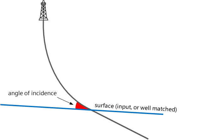
The angle of incidence, which is exported alongside the residuals in the CSV file, is the smallest angle between the wellbore and the surface. click to enlarge
Creating a point set from all residual data (only for marker residuals)
With the 'Create point set(s) (in Data folder) with all marker residual data' option (![]() ) located at the upper-right side of the residual table you can create, per surface, a point set from marker residuals. The nodes of the point set represent the marker locations, the residuals (pre and post well matching) are stored as properties of the point set. Using point sets to store your well matching results allows you to create extra copies of your well matching actions (for reporting purposes) and to perform advanced analysis of the residuals (trends, scatter plots) and the angle of incidence.
) located at the upper-right side of the residual table you can create, per surface, a point set from marker residuals. The nodes of the point set represent the marker locations, the residuals (pre and post well matching) are stored as properties of the point set. Using point sets to store your well matching results allows you to create extra copies of your well matching actions (for reporting purposes) and to perform advanced analysis of the residuals (trends, scatter plots) and the angle of incidence.
The point set is stored in the Data folder under the respective event type (Horizons, Faults, Unconformities, etc). The point set name is assembled as follows:
Event name_WMResults (Source folder, Target folder, Marker set): Input representation
To create the point set(s)
- Click the 'Create point set(s) (in Data folder) with all marker residual data' icon.
- Verify that per event, a point set is created in the JewelExplorer > Data folder, under the respective event type (e.g. Horizons, Faults, Intrusions, etc.).
-
The point set contains the following properties:
- Depth (default)
- WM Residual Pre
- (Optionally) WM Residual Post
- Wellbore Names
- WM Angle of Incidence Pre(*)
- WM Angle of Incidence Post (if you applied the well matching with 'Apply' or 'OK' on the form)
(*) See explanation of this angle under 'Exporting residual data' above.
- Visualize the point set and property of your choice in the 3D View by checking the boxes in the JewelExplorer.